 |
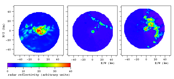
Figure 11 Examples of digitized radar images, showing varying radar reflectivity across convective cloud systems.
|
A poster presented at the WCRP/SCOR Workshop on Intercomparison and Validation of Ocean-Atmospere Flux Fields in Washington DC, 21 - 24 May 2001
However, 70% of the earth's surface is covered by ocean, and the ocean of the tropics and subtropics, which between 30°S and 30°N make up 50% of the earth's surface, plays a decisive role in the global freshwater and energy budget. Obviously, some way has to be found to obtain reliable rainfall data over the ocean.
Recognising the need for better rainfall information over the tropical ocean, the global climate research community launched the Tropical Rainfall Measurement Mission (TRMM). When supplied with accurate calibration algorithms this mission can produce reliable global estimates of tropical rainfall. Most of the ground truth data for the algorithms has to come from the ocean.
Ships of opportunity regularly include rainfall data in their voluntary weather reports. The data base created by these volunteer observers cannot be underestimated. But modern ships traverse the tropical oceans in a matter of days. Their rain record is never long enough to allow for integration in time. The work reported here is based on the concept that integration in space at sea can achieve what integration in time achieves on land. Every ship of opportunity carries a navigational radar. If it is possible to extract rainfall information without disturbing the navigational use of the radar, integration over the radar image can potentially provide a reliable measure of regional rainfall on a routine basis.
In August/September 1996 R/V Franklin performed a triangular pattern around a drifting buoy in the eastern Indian Ocean near 2°S, 93°E (Figure 1), towing a Seasoar CTD. Rainfall was measured with an optical rain gauge on the buoy, and on the ship by video taping the radar screen every 10 minutes at 25 frames/s. The Seasoar-derived surface salinity correlates well with the radar-derived rainfall (Figure 2).
Composite images were then constructed from one full rotation of the radar antenna (Figure 3) and converted into digital images. The low resolution threshold of the radar screen allowed only 1/0 discrimination (rain or no rain). Radar clutter in the vicinity of the ship was suppressed and corrected where possible (Figure 4).
Calibration was achieved in two ways.
Results from this experiment are reported in Lebedev, I. and M. Tomczak (1999) Rainfall measurements with navigational radar, Journal of Geophysical Research 104, 13,697 - 13,708 (1999)
To provide a "first look" facility, the recorded file was immediately processed by averaging all revolutions and displaying the average on the PC screen. Quantitative processing was done after the voyage.
The purpose built data acquisition interface converted the analog radar signal into digital data with 6 bit resolution, allowing for 64 levels of radar intensity. The 10 revolutions were averaged into bins of 1.5° width and 1.2 km length, determined by the technical specifications of the radar.
The averaged data were geo-located, using the ship's heading and position, and interpolated to a rectangular grid with 1 km grid size and north-south/east-west orientation.
Various versions of radar data were compared with various versions of buoy data for calibration: Gaussian averages of radar reflectivity around the buoy positions with radii from 250 m to 1 km in steps of 125 m were correlated with buoy rain gauge data averaged over intervals from 1 minute to 16 minutes in 1 minute increments, where the average was always centred on the time of the corresponding radar observation.
Highest correlation was achieved with a buoy time average of 3 minutes and a Gaussian radar reflectivity average with a radius of 875 m. These parameters were used to determine, through logarithmic correlation, the constants a and b in the relationship Z = α R β between the measured radar reflectivity factor Z and the rain rate R observed at the buoys (Figure 8). Points close to zero (representing radar scatter in the absence of rain) were removed before the correlation.
Unfortunately the period of the experiment coincided with an unusually dry spell in the north Australian monsoon season. The monsoon rains usually arrive in northern Australia in October. During 1999 they had clearly started before mid-November. The buoy moorings were deployed on the 28th of November, and during the first week after deployment reasonable rainfall was received around the Gulf of Carpentaria. The second week of the experiment was extremely dry (Figure 9). The period with useful data was therefore shorter than 1 week. Data analysis is continuing, focussing on comparison with TRMM data (Figure 10).
|
Figure 11 Examples of digitized radar images, showing varying radar reflectivity across convective cloud systems.
|
Navigational radar can of course never achieve the accuracy and resolution of dedicated weather radars. The advantages of navigational radar are
| First Experiment | Second Experiment | |||
| radar model | JMA-627-7 | radar model | Furuno | |
| Wavelength | 3 cm | Antenna | slotted waveguide array 20 revolutions per minute length = 6.5 ft horizontal beam width = 1.23° vertical beam width = 25° attenuation = 26 dB |
|
| Polarization | horizontal | |||
| Rotation | ~ 22/minute | |||
| Beam width at Ł3dB point | 1° horizontal 20° vertical |
|||
| Sidelobe level | -26dB within ±10° -32dB outside ±10° |
RF Unit | frequency = 9,375 ± 30 MHz peak output = 20 KW pulse length = 0.08 and 1.0 ms pulse repetition rate = 800 Hz |
|
| Gain | 31dB | |||
| Pulse width / PRF | (6,12nm) 0.7ms/1000Hz (24,48nm) 1.0ms/750Hz |
|||
| Manufacturer | Japan Radio Co. | |||
| PRF = pulse repetition frequency | ||||